MSP430 Bicolor LED Clock
When Texas Instruments announced their new Launchpad development platform last month, I jumped on it as fast as I could, considering how hard their e-store went down. The price was right ($4.30), but more importantly, I’ve been looking for a way to get into their platform, because I see a lot of future in it.

The MSP430 microcontroller is specifically designed for low-power battery applications, and the Launchpad finally provided me with the tools I need to get into the platform. I’ve been wanting to give a battery powered project a shot, but my first project based on the MSP430 core seemed pretty obvious; time to build another clock, but this time battery powered.

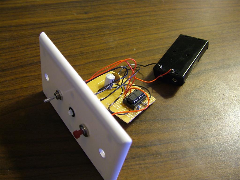
I’m a big fan of minimalism, so I decided to go with a single bicolor LED display, and minimal controls for setting the time.
- The switch is to select the mode, between displaying the current time, setting the current hour, and setting the current minute.
- The LED is a red-green LED, which displays the current time upon request. Green flashes mean 10, yellow 5, and red 1, so the time 5:28 would be displayed as YELLOW [PAUSE] GREEN GREEN YELLOW RED RED RED (5:10+10+5+1+1+1). It also adds an alternating red-green pattern to the time in the PM.
- The push button activates the display, bringing the controller out of sleep mode long enough to either blink out the current time, or update the time based on the mode select switch.
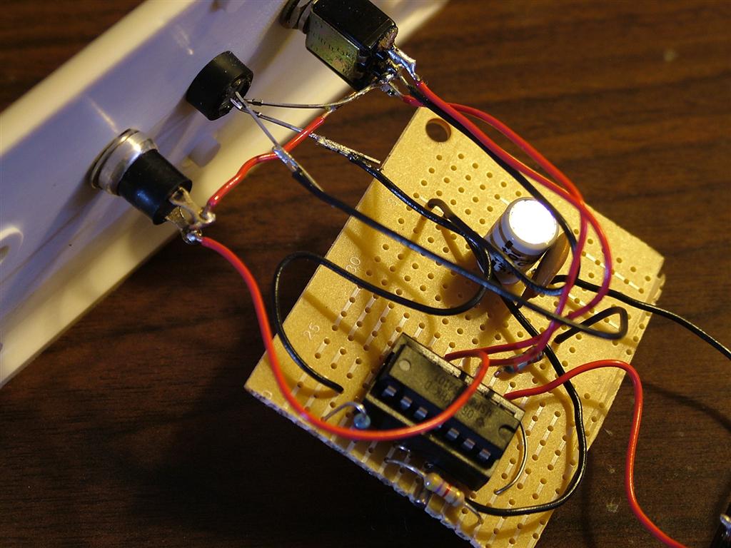
The internals are nothing surprising: small piece of perf board for the controller and the few passives, and a 2xAA battery holders for power, which should last for a VERY long time (rated current draw during sleep is sub-1μA).
Parts list:
- MSP430G2101 controller (though any MSP430G2 controller with 1k+ of flash should work
- 32.768kHz quartz crystal. I happened to only have a 6pF one, instead of the more standard 12.5pF, but the crystal oscillator in the MSP430 can be adjusted in software to match either.
- perf board large enough to fit the controller
- 1 14 pin DIP3 socket
- 2x 120Ω resistors for the bicolor LED anodes
- 1 bicolor red-green LED
- 1 5mm LED panel mount
- 1 100μF and 1 0.1μF capacitor for power filtering on the perf board
- 1 2xAA battery clip
- 1 4k pull-up resistor for the reset pin
- 1 NO (normally open) push button
- 1 SPDT (single pole double throw) switch with center off position
- 1 gang box and blank cover
The gang box enclosure is particularly unique to this project. If you buy “new-work” gang boxes, they’re only 25-50 cents a piece, depending on if you get the 18 or 20 cu in sizes. Add to that a 50 cent blank cover, and you have a half decent project box for little more than a dollar. The one thing to be very careful of is the fact that the white plastic is INCREDIBLY brittle, even when brand new. You must be very careful when drilling into it, due to its tendency to crack. Another option is to instead mount the interface on one of the other sides, since the blue plastic box itself drills very nicely.
Schematic:
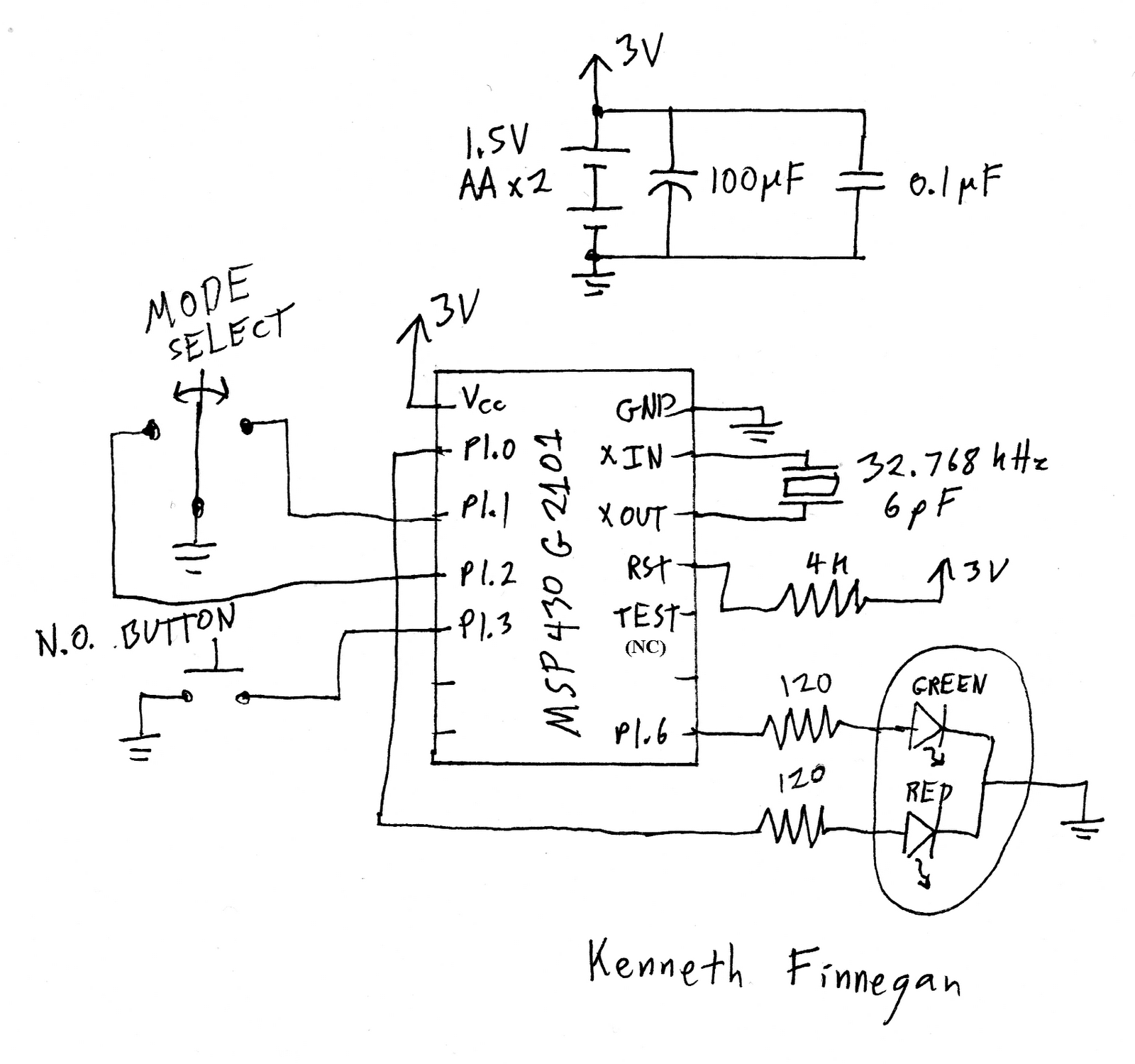
Note: TEST should not be pulled high with the reset line. This makes for unstable uC starting.
Update 9/17/2010: Fixed the error in the schematic, and it turns out this project has been reimplemented by one of my readers. :-)