Addressable I2C Arduino Motor Driver
For my senior project for UC Davis, I needed to have several interchangeable modules that can control typical DC hobby motors, and monitor their position via an infrared sensor. This design isn't particularly optimized, since an Arduino is a little over-kill for doing little more than listening on an I2C bus for rotation commands, and then handling the control loop between the motor H bridge and IR sensor, but it was fast and super easy to hack together, and makes for a good reference design to start with.
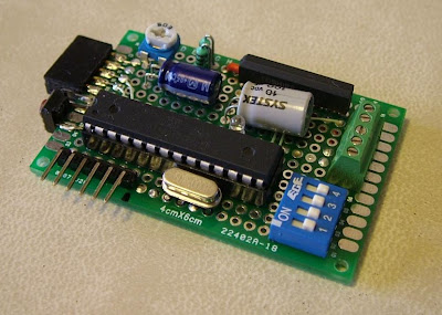
The main components to this driver board are, from left to right:
I'm unable to release my specific software that I developed for this board, but the Wire library makes it very easy to program I2C slaves using the onReceive and onRequest hooks. You'll need to come up with some sort of command code set between your master and these slaves, but writing the handler functions and state machine to allow for issuing rotation commands, and even polling the drivers for their current status, shouldn't be too hard.
What isn't shown is the motor and sensor attachment. I used 0.1" screw header to make them somewhat detachable, and used a motor and IR sensor from Pololu. By using a dab of black oil-based paint on the aluminum mounting hub and a simple low-pass filter, it is fairly reliable to watch for the black dot using one of the Arduino's ADC channels.
Pololu's IR sensor board is based on the QRE1113 reflectance sensor, which is both an IR LED and an IR phototransistor in a single (very small) package. If Pololu's breakout board doesn't happen to meet your needs, building your own will only take that part and two resistors.
Having access to an oscilloscope makes tuning the driver easier, since the reflectance sensor is somewhat picky about how far and at what angle it is from the encoder wheel. Properly positioned, you can get a 4V pulse from a dark spot on the wheel, which means you could likely rely on a digital input, but I found using an analog-to-digital converter more reliable.
I built my three boards by hand from high quality perf board, but only because I didn't have enough time to spin a custom PCB for them. If you're making more than one or two, you really probably want to make a board, because building three of these and debugging them got a little tired.
And yes, I agree, those 0.1" screw blocks are adorable.
The two rows of female header are connected in parallel, since I2C is a multidrop bus, so these boards can be chained together, saving wire.
The main components to this driver board are, from left to right:
- A 5x2 female socket for GND, 5V, 12V (for the motor), and SDA and SCL for the I2C bus. This connector is doubled up so simple 5 conductor cables can be chained from board to board.
- A reset button and 6 pin serial port for the Arduino.
- An ATMega328 and all the supporting circuitry needed to have it run the Arduino software stack. I flashed the bootloader on the ATMegas using my previously mentioned target board.
- A 500k trim pot, which is used as a voltage reference for the voltage regulator inside the H bridge. A better voltage reference would use something more regulated than a trim pot, since if the input voltage doubles, the drive voltage doubles. Ideally you should be able to set the drive voltage to a specific voltage, instead of a fraction of the rail voltage, but again, quick and dirty here.
- A Toshiba TA7291SG H bridge motor driver. This is called an H bridge because it is four transistors arranged like the legs of an H around the motor (which is on the center beam), allowing you to selectively apply current in either direction, isolate the motor (to let it coast), or short the motor to ground (which acts as a brake). This chip comes in an easy-to-solder SIP9 package, and can handle 400mA.
- A 4 position DIP switch, which the Arduino checks to see what I2C address to use, such that you can chain up to 16 of these onto a single bus and be able to control them independently.
- A 5 position screw terminal block for the two terminals of the motor, 5V, GND, and the returned output of the analog reflectance sensor used to monitor the motor's speed.
I'm unable to release my specific software that I developed for this board, but the Wire library makes it very easy to program I2C slaves using the onReceive and onRequest hooks. You'll need to come up with some sort of command code set between your master and these slaves, but writing the handler functions and state machine to allow for issuing rotation commands, and even polling the drivers for their current status, shouldn't be too hard.
What isn't shown is the motor and sensor attachment. I used 0.1" screw header to make them somewhat detachable, and used a motor and IR sensor from Pololu. By using a dab of black oil-based paint on the aluminum mounting hub and a simple low-pass filter, it is fairly reliable to watch for the black dot using one of the Arduino's ADC channels.
Pololu's IR sensor board is based on the QRE1113 reflectance sensor, which is both an IR LED and an IR phototransistor in a single (very small) package. If Pololu's breakout board doesn't happen to meet your needs, building your own will only take that part and two resistors.
I built my three boards by hand from high quality perf board, but only because I didn't have enough time to spin a custom PCB for them. If you're making more than one or two, you really probably want to make a board, because building three of these and debugging them got a little tired.
The two rows of female header are connected in parallel, since I2C is a multidrop bus, so these boards can be chained together, saving wire.


