Designing and Building a 2m Low Pass Filter
I’ve been playing with the DRA818V modules that have been making quite a stir in the amateur radio world at the moment. I haven’t gotten one on a spectrum analyzer yet, but I have reason to believe that it will require a low pass filter to be RF legal. I’ll write more about that once I get a look at it, but figured I’d first built myself a low pass filter in case I need it (if not for these modules, but some other VHF project in the future).
My process for building a low pass filter went as follows:
- Select the type of filter and cutoff frequency desired
- Look up normalized coefficients in the ARRL Handbook
- Divide these coefficients by the cutoff frequency
- Convert the inductances into turns on some core and capacitors into the nearest values
- Build the filter.
Since I wanted this filter for 2m, the highest frequency I’m interested in passing is 148MHz, so I selected a cutoff frequency of 150MHz. In hind-sight, this was a poor choice, since a -3dB point only 2MHz above the band caused for a lousy insertion loss. A better choice would have been 10% higher than the top of the band, so 148MHz * 1.10 = 162MHz
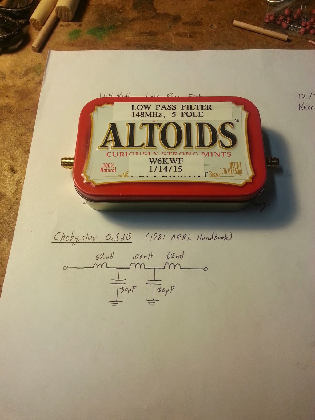
I decided to build a 5 pole T configuration Chebyshev filter with 0.1dB of ripple.
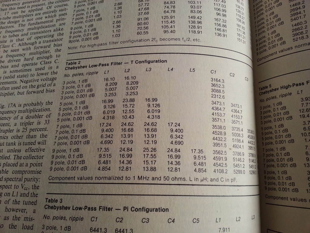
Looking this filter up in a random copy of the ARRL Handbook (1981, but any recent one will do), it gives the component values needed for a 50 ohm filter at 1MHz. I’m also building this for 50 ohms, so all I need to convert is the frequency by dividing by 162MHz.
- L1 = 9.126uH / 162 = 56nH – 3 turns on 1/4” air core
- L2 = 15.72uH / 162 = 97nH – 5 turns on 1/4” air core
- L3 = 9.126uH / 162 = 56nH – 3 turns on 1/4” air core
- C1 = 4364.7pF / 162 = 27pF – 30pF on hand
- C2 = 4364.7pF / 162 = 27pF – 30pF on hand
To convert the inductance values into solenoid designs, I have an old magazine article from the 70s that published a whole table of different diameters of air wound inductors.
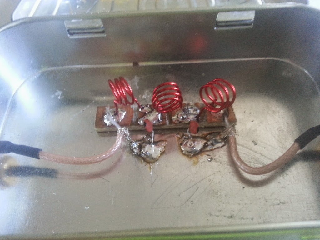
For extra blog cred, I built the filter in an Altoids tin with SMA connectors on each side. The four solder pads were formed from a strip of copper clad with three hacksaw cuts.
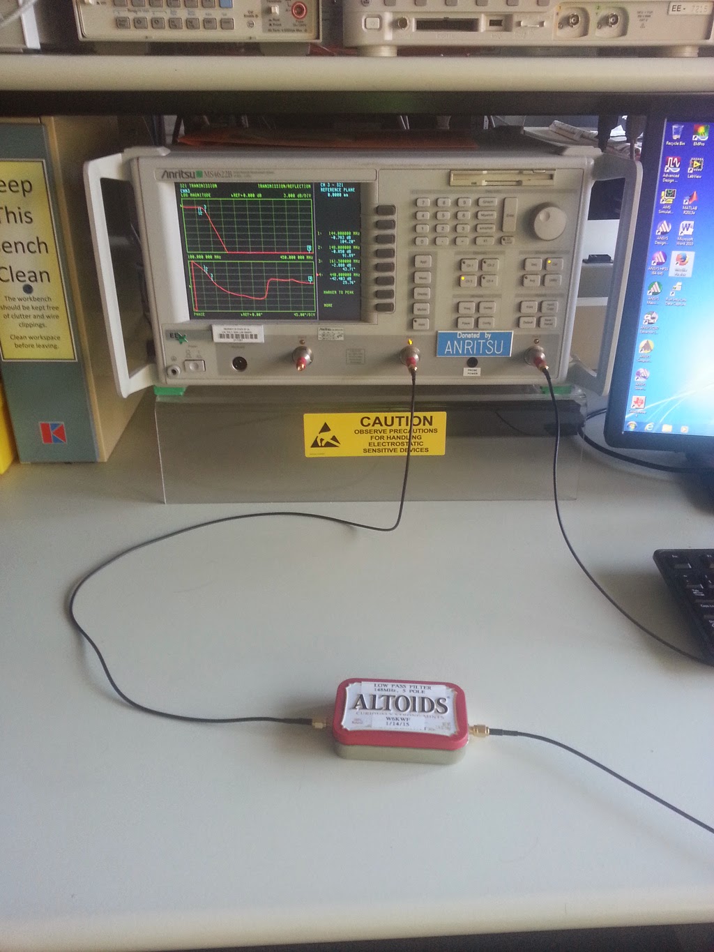
Next step was hooking this up to a vector network analyzer to see how far off I ended up, which is when I realized that 150MHz was a poor corner frequency choice. Reforming the inductors and taking a turn out of L2 got me closer, but I would have ended up with better performance if I had designed it all correctly from the start.
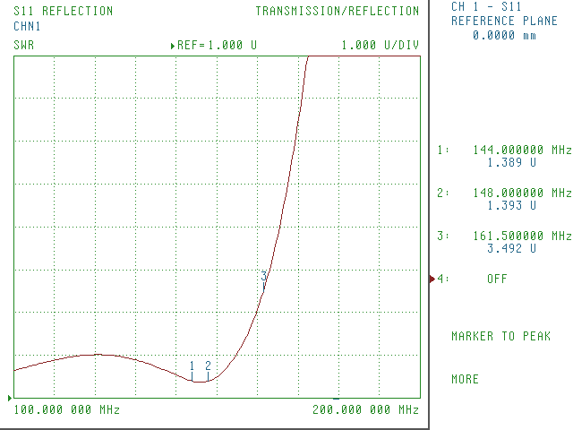
The SWR at 2m is about where it’s expected to land at 1.3
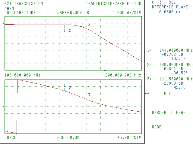
The insertion loss at 2m isn’t so great at 0.8dB. This would be improved by better component layout, but I built this filter kind of sloppy. It does suppress all the harmonics of 2m as expected. I only bothered to note that 200MHz was down ~23dB, so 440MHz will be well below that.
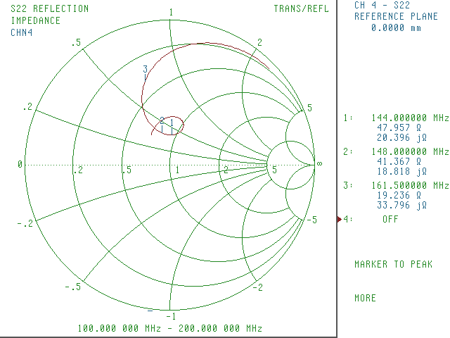
In an ideal world, points 1 and 2 on the smith chart would fall at the center (1,0), but 45+19j ohms is close enough for me.
Now once I get to the point of experimenting with keying up my DRA818V modules, I’ll have a nice LPF on hand in case the harmonics do end up too high for on the air testing.