PK-88 TNC Hardware Modifications
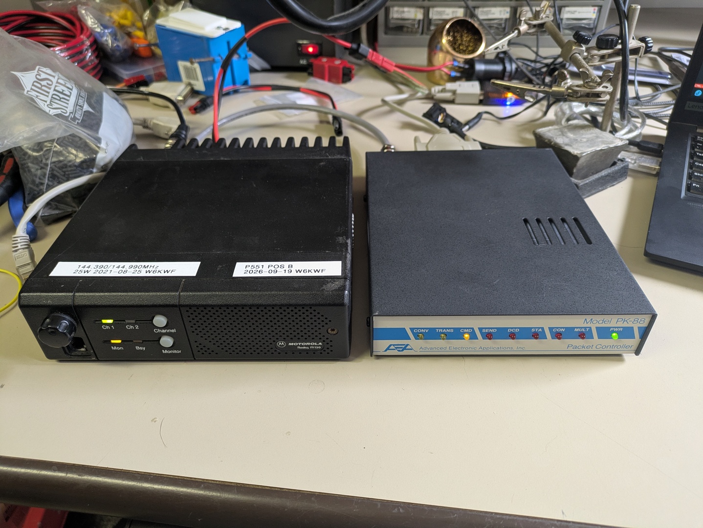
As is typical for stories on here, through a long series of events I ended up in kind of the perfect position to build APRS infrastructure supporting Northern California. On the APRS side, I had (more than a freaking decade ago now!) put together my Masters thesis on APRS and the protocol design of it. While working on that, I played around with a few different Terminal Node Controllers, which are essentially APRS’ version of external modem (plus optionally a lot of the network protocol intelligence as a historical artifact of the early days of packet radio pre-dating the ubiquitous home personal compute). I had developed affection for the AEA PK-88 in particular for a few reasons; primarily that its modem performance seemed quite good in testing, the circuity is Z80 based and well documented, and finally that with a little patience obtainable on eBay for less than $50.
On the Northern California side, I’ve gotten to know several of the repeater infrastructure folks who own and/or operate radio sites and/or repeater systems. Most notably, the Salinas Valley Repeater Group has been particularly keen on building out radio infratructure in the area, and tacking an APRS digipeater / Internet gateway onto one of their sites is logistically quite straight forward.
APRS digipeater / I-gates perform two functions for APRS. On the RF side, being a digipeater means that from someplace up high, the station is able to listen for beacon packets from lower level APRS stations and repeat them on the same 144.390MHz channel with higher power and a better antenna to enable other APRS stations in the area to hear them. On the Internet side, as long as the station has an Internet connection, all decoded packets get sent up into what is called the APRS Internet System (APRS-IS) to enable anyone online to get a comprehensive view of all APRS traffic happening globally. Since APRS is a single channel half-duplex system, you avoid all of the complicated and expensive RF combiner / duplexers needed on regular repeater infrastructure, and it’s very easy to find an idle 144MHz antenna somewhere at the site and hook a digipeater up to it with a single stage bandpass filter to protect my radio from the rest of the radio nonsense going on at a real commercial radio site.
So anyways, long story short, not only has SVRG been asking me to provide them with APRS digipeaters for them to stick up at really nice high-level radio sites, they’ve been asking me for SEVERAL APRS digipeaters. A lesson I’ve learned several times over across my infrasture hobbies is that when you’re tasked with managing not one or two of a system, but a handful up to several dozens (looking at you, 40+ MicroMirror server locations) there is a huge force multiplier in religiously making every copy of the system as identical as possible.
The entire digipeater hardware stack warrants its own blog post, but as a first piece of it, I selected the AEA PK-88 as my “standard” TNC modem that I’m using in each and every radio site. As I have already built several of these digipeater systems and now have several more… “on order?” I’ve needed to get more organized on the list of little hardware modifications I make to the TNC as some quality of life improvements.
Jumper Settings
I set the jumpers in the standard way, which is oddly poorly documented in the AEA manual, other than saying “it comes from the factory set correctly for most operations” but when I’m getting these things off eBay from other hams who have done lord knows what to these things, the need for this list. Note that for orientation I’m assuing the TNC is facing you, so the “front” of the circuit board has the status LEDs, the right side of the circuit board has the LM7805 heat sink, and the radio interface plug is on the “back left” corner.
JP1 & JP2 - My best guess is that these are circuit board trace jumpers for adjusting the memory mapping when using two 16kB SRAM chips, which is no longer required since 32kB SRAM chips don’t carry a significant price premium to two lower density SRAMs.
My second best guess is that the AEA developers were worried about fitting all of the firmware in the 32kB 27C256, so this might have been a backup plan for using IC11 to give the TNC 48kB of ROM.
I’ve never seen a PK-88 come configured with anything installed in IC11, so leave as printed on the circuit board.
Exactly how only the 74LS139 and the jumpers are supposed to map two chips into the upper half of the Z80 memory map is very unclear to me, so I wouldn’t be surprised if additional fly wires were originally required.
JP3 - This jumper allows you to connect the host DCD signal to the CON connected status line instead of just being strapped high.
Since KISS doesn’t rely on the TNC’s AX.25 network stack, we don’t care about the connected status of the internal AX.25 stack.
The jumper is between the middle and rear pins.
JP4 - This set of three jumpers enables you to connect an external modem to pins 14-16 of J1 instead of using the internal 7910 AFSK modem.
Since I’m using this TNC specifically as a Bell 202 modem for APRS, I’m keeping it set for using the internal modem.
All three jumpers are between the middle and front pins of each set of three.
JP5 - This adjusts the polarity of the Push to Talk signal from the TNC out to the radio.
Motorolas (as well as practically every radio I can think of) rely on an active-low signal, where the PTT line on the radio is connected to ground to key up the transmitter.
the jumper is between the middle and left pins.
JP6 - This jumper is used to connect/disconnect the battery from the +5BB rail, so if you ever want to completely clear the settings from the TNC or disable the ability for the TNC to remember settings when external power is removed, open this jumper.
I leave it installed so the TNC stays in KISS mode across power cycles.
JP7 - This adjusts something about the SCC generating interrupts for the host serial port.
I have no clue.
I leave the jumper between the middle and right pins.
JP8 - This is a solder jumper on the PCB for looping DSR back to pin 10 on the serial port.
Leave open.
JP9 - This is a solder jumper for grounding the Squelch line on the radio interface P2.
The purpose of either JP9 or the SQ line has been very unclear to me, so I always leave it open.
I have also received several PK-88s which had an additional jumper soldered between the rear ends of R5 and R7 for connecting the RTS and DSR signals on the serial port. I’ve always removed them, but the fact that I’ve gotten multiple with the same mod is quite interesting.
E1744 Firmware Update / Reburn
As far as I can tell, the last version of the firmware released for the PK-88 was version “E1744” with the power on welcome date of August 23, 1991.
Thanks to the luxury of having both a MiniPro PROM burner and a UV eraser on hand from various other projects, as a policy I always replace the existing EPROM with a freshly burned one with the latest firmware.
Not only does the behavior of the KISS ON command slightly change across some of the earlier firmware releases, the original EPROMs are getting well over 30 years since they were originally burned, so for the sake of minimizing the risk of future failures in the field due to bitrot, I reburn the ROMs.
As an aside, when the TNC is powering on, it performs a checksum across the entire ROM. Historically, AEA shipped each firmware version with the expected one byte checksum for it, but it appears that they later moved to a method where the expected checksum for all releases is $00, so you can ignore the mentions of the firmware checksum in the manual and as long as you see no mention of the checksum in the power-on message it passed. If the firmware doesn’t checksum to $00, I believe it will print a warning with the calculated checksum but will continue to boot anyways, so I can imagine you could experience bitrot on the EPROM and continue successfully using the TNC for quite a while.
Battery to SuperCap Replacement
The settings on the modem, which for me is namely just that it should sit in KISS mode, are stored not in a persistent EEPROM or FLASH chip, but actually in SRAM which only survives power getting removed from the TNC by the fact that it has a diode combiner falling back to a lithium coin cell battery which is soldered onto the motherboard to keep the SRAM alive persistently. An incredible demonstration of exactly how little power it takes to retain data in SRAM that just a coin cell battery can keep the contents alive, but these coin cells are also getting up into the many decades old, so they warrant replacement. Normally if these were just CR2032s in a coin cell socket I’d drop in a new one like I do on every rack mount server that moves across my bench, but these are soldered onto the board and I’d much prefer to guarantee that I never need to go back into these TNCs once they’re deployed, so I’ve opted to replace the orginal coin cell with a 5.5V super capacitor!
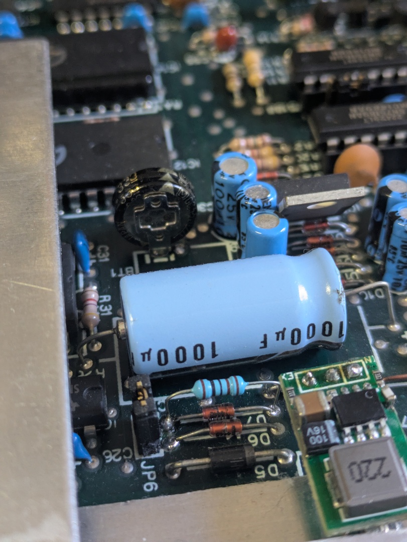
These things are very neat little capacitors which are purpose build for exactly this purpose of being a coin cell replacement without the chemical reaction. Normal super caps are typially good for 2.7V and ALL the amps, but there exist little coin cell style super caps which are “only” 0.2-1.5F (no micro, just whole ass Farads) with a relatively high input impedance. Just charging one of these capacitors and soldering it as a replacement for the lithium battery would give you several weeks of backup power, but by soldering a 1k - 10k resistor piggy back on top of diode D7 on the TNC you turn the bbRAM 5V rail into a trickle charger for the capacitor when the TNC is being powered from wall power.
So as long as the TNC doesn’t sit unpowered for more than a few months, it successfully retains all of its settings. And even if it did sit cold for long enough that the TNC lost all of its custom configurations, I’m operating them atached to a computer so I can open the serial port and re-apply all the same settings again.
LM7805 Switch Mode Replacement
While the input ~13V to the TNC is needed for the charge pump generation the +/-10V for the RS-232 interface, most of the power used by the TNC goes through a 5V linear voltage regulator, so more than half of the power consumed by the TNC is burned off as heat on the heat sink which takes up about a third of the space inside the enclosure.
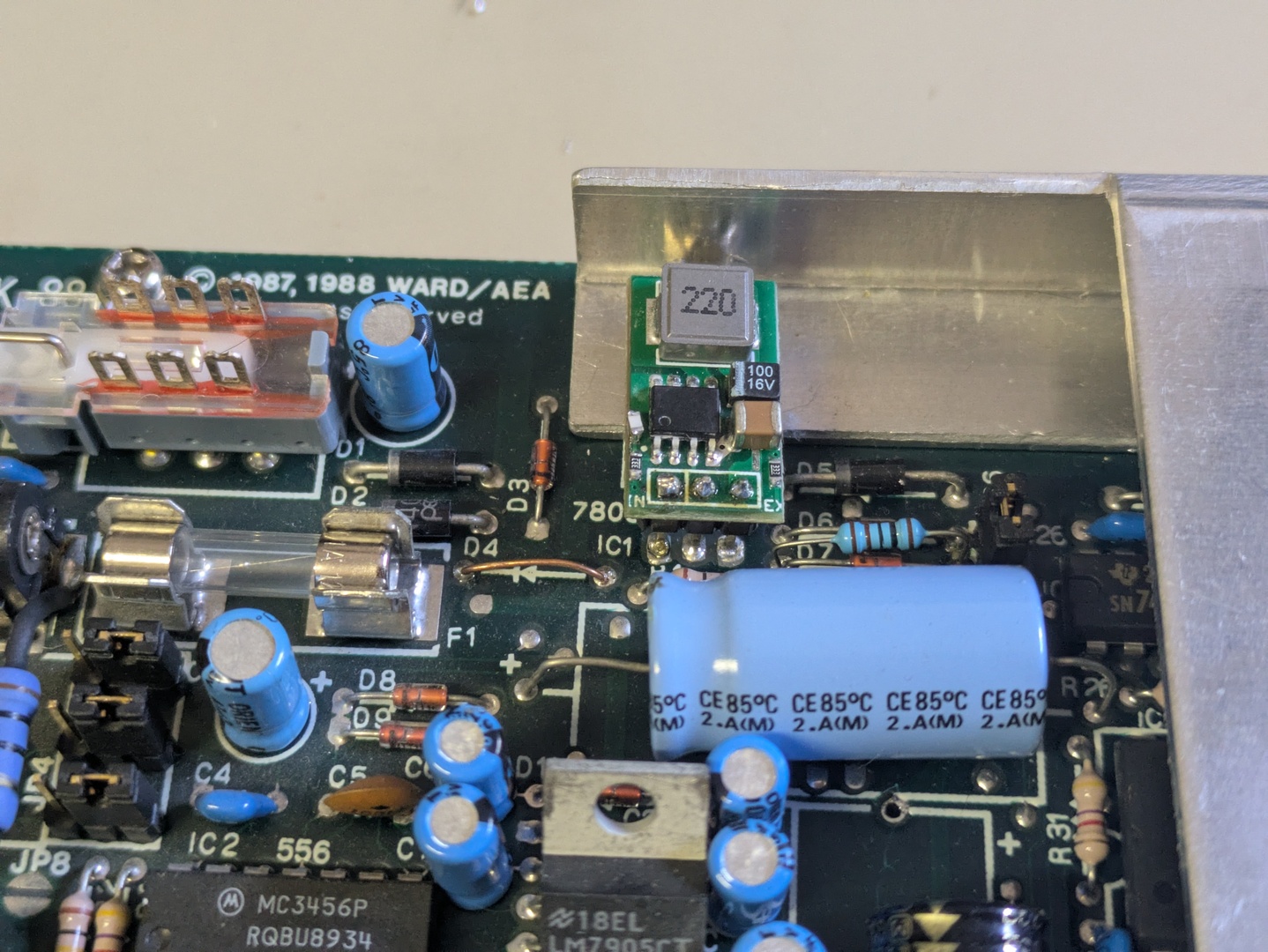
Thankfully, we aren’t living in the 1980s anymore, and you can actually buy super cute little switch mode buck converter modules as drop-in replacements for 7805s. I was originally introduced to these by a MuRata sales rep wandering past my desk at work and tossing a few on my desk, but I’ve found the generic ones from Amazon or eBay are good enough for handling the few watts used by the TNC’s digital logic. This causes the TNC to run much cooler, which is probably a good thing for the capacitors hanging out inside the enclosure as well as being more power efficient.
I have seen some of these buck converters have trouble with the floating ground originally used in the PK-88 for the LM7805 to compensate for the diode drop to the +5BB rail. Because the TNC uses a pair of diodes to combine the input power’s 5V with the backup battery for the SRAM, it puts another diode D4 in series between the ground pin of the voltage regulator and actual ground, so the 7805 is actually putting out 5.6V, which is then dropped by D5 and D6 down to the 5V expected by everything else in the circuit. Since switch mode power supplies tend to have somewhat more… dynamic ground currents than a linear voltage regulator, I’ve been modifying the voltage divider on the 7805 replacement module to output more like 5.7V, replace D4 with a jumper wire, and simply rely on D5 and D6 dropping us down to the 5V expected. In my case, the feedback resistor divider on the regulator modules is 10.5k + 33k and I’m stacking a 51k resistor on top of the 10.5k resistor to nudge the ratio in the right direction, but lord knows how consistent these modules are across batches. If you’re not comfortable stacking a second 0603 surface mount resistor on top of the first one… they make little buck converter modules with a potentiometer on them as well, so you can just dial in 5.6V and use a dab of glue on the knob to commit to it.
Power In on P2.p4
While I have always been a huge fan of the 5.5mm x 2.1mm barrel jack connectors as a DC power standard, I have never been that much of a fan of it being a connector which is only held in by spring force and optimism. Radio sites tend to be far away and hard to get to, so I’m really invested in my radio systems not going offline and requiring a site visit only because the power jack fell out and needs to be pushed back in. Thankfully, the Motorola radios I’ve standardized on have a 16 pin accessory interface connector which is much more flexible than the standard mini-DIN plug amateur radios tried to standardize on, and it includes a 12V output from the radio, so it is possible to have the radio feed power into the TNC over the same interface cable as is used for transmit and receive audio as well as the push to talk signal.
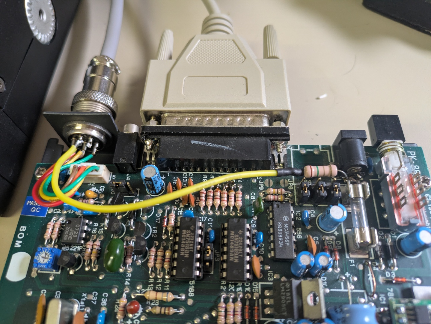
The PK-88 uses a screw ring retained 8 pin connector, where pins 4-6 are unused and unconnected. I solder a wire from P2.p4 running to the back of J3 (the power input barrel plug) with an in-line 1.5 ohm 1W resistor, then build my radio interface cables routing their aux 12V output to match. The reason I put a 1.5 ohm resistor in-line on this wire is because the Motorola radios have a little 2A pico fuse on their aux 12V line, and I’ve seen the 1000uF filter capacitor on the PK-88 blow that fuse if the radio 12V rail comes up too quickly, so we’re doing some basic in-rush limiting here.
One big disadvantage of this mod is that the radio interface P2 plug is mounted to the TNC chassis, so while the five original interface lines are connectorized on J2 for the circuit board, this additional wire to pin 4 now forever connects the PCB to the bottom of the enclosure, so I make sure to include enough slack to be able to work on the PCB again if needed. Or, you know, just embrace the idea of desoldering the wire if you ever need to.
Labeling
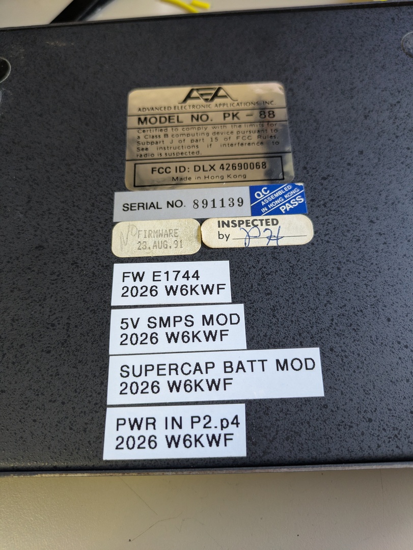
One thing I’ve found extremely helpful when making all of these modifications to my TNCs is that it’s nice to label the outside of equipment with what mods I’ve made to them and when. Label tape is cheap compared to the amount of time I’ve saved myself not needing to open up and reverse engineer things I’ve done in the past and forgotten about.