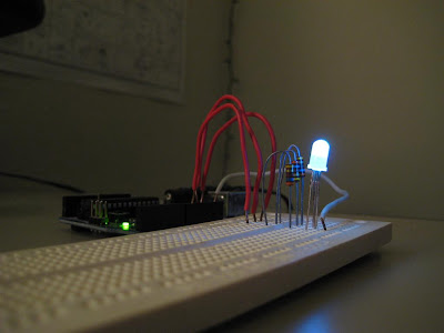
Arduino RGB LED Mood Light
I wasn't feeling creative today, so I decided to hack together the classic mood light, where you take a Red-Green-Blue LED and have it fade from color to color. I did this back when I originally got the RGB LED, but didn't do a very good job on the algorithm for the colors.

The algorithm I used this time was a little better, but still needs a little work. As it stands now, it picks a new color as follows:
Once the target color has been selected, all that's left is to drift to it from the current color, to create the soothing ebb of color.
My video camera isn't very good at recording the color of a light source, but if you watch the breadboard it's plugged into, you can see what's going on, color wise. (If you're reading this in Facebook, you're gonna need to click through to the original post. Yeah, right there, at the bottom, right above the comments, theeere you go...)
Link to the source code.
The simplest circuit diagram you've ever seen:

Note: Apparently the common-cathode RGB LED (where the LED's all share one cathode) I have is uncommon. Reconfiguring this circuit to operate with a common-anode LED is relatively trivial, since AVR I/O pins can both source and sink current. Just connect the anode to 5V, and subtract the desired PWM value from 255 in the source code.

The algorithm I used this time was a little better, but still needs a little work. As it stands now, it picks a new color as follows:
- Generate a random number between zero and the maximum intensity and assign it to the target value for a random one of the three colors.
- Generate a random number between zero and the maximum minus the target for the first, and assign this number to the next color's target value.
- Subtract both of the previous target values from the maximum, and assign this to the third.
Once the target color has been selected, all that's left is to drift to it from the current color, to create the soothing ebb of color.
- Is the current red level higher or lower than the target? If so, add or subtract one to get closer.
- Write out the current state to the PWM pins on the Arduino.
- Pause for 10ms
- Move on to blue, then green, pausing another 10ms after each.
- After moving all three one value up or down, if we're still not at the target color, loop back and repeat.
- Once the target color is reached, pause for 2 seconds to let the viewer enjoy the new color, then select a new target color and repeat the entire cycle.
random() a couple times is a lot easier when you aren't feeling creative.My video camera isn't very good at recording the color of a light source, but if you watch the breadboard it's plugged into, you can see what's going on, color wise. (If you're reading this in Facebook, you're gonna need to click through to the original post. Yeah, right there, at the bottom, right above the comments, theeere you go...)
Link to the source code.
The simplest circuit diagram you've ever seen:

Note: Apparently the common-cathode RGB LED (where the LED's all share one cathode) I have is uncommon. Reconfiguring this circuit to operate with a common-anode LED is relatively trivial, since AVR I/O pins can both source and sink current. Just connect the anode to 5V, and subtract the desired PWM value from 255 in the source code.

