Lamp Controller - Phase 1
WARNING: This project uses high (120VAC) voltage, and thus should not be duplicated without a strong understanding of what one is doing, and a handle on one's compulsive need to touch things. Not only am I in no way liable for what you do with this information, I would be VERY SAD if I found out someone had killed themselves inspired by my project blog.
ALSO NOTE: Since all of the 120VAC equipment I build plugs into the wall and is not hard wired, I in NO WAY violate the NEC, as this is all "temporary" wiring. This means I do NOT want to read any comments about how this will void my fire insurance or how unsafe this project is, without a specific critique as to how to improve it (A choice place for improvement would be in the TRIAC triggering circuit, for which I could not find a concise application note as to how to use the TRIACs, which is why the schematic is deliberately vague there. I've seen a lot of crazy stuff, including BJTs, capacitors, and several resistors, with no explanation as to their purpose. I very carefully watched my circuits for the first few days and severely derate it.)
This is an on-going project involving the lighting situation in my room. I live in an apartment which doesn't have any overhead lighting in the bedrooms, which means I have to light my room with several lamps scattered throughout the room. This would be fine, except that the outlet controlled by the light switch is in quite possibly the least useful place based on my room's arrangement. This means all of my lamps are individually controlled, and the light switch controls none of them. One of them didn't even have a switch on it, so I had to hack one together from spare parts.

This post covers only the initial, crude version of this project. At this point it does nothing other than turn the lights on and off at command. Future enhancements will be documented as they happen.
Video:
Currently, there is individual buttons for each of the three lamps, and a circuit to monitor the switched outlet across the room. Pressing any of the buttons will toggle the respective lamp. A positive edge on the light switch will turn a select two of the lamps on, regardless of the current state of the lamps. A negative edge on the light switch will turn off all lamps. This makes the light switch useful again, as it allows it to turn on a useful set of lights on entrance to the room, and turn off all lights on exit. If the light switch is in the wrong position (up when a positive edge is needed), all you have to do is switch it down, and back again.
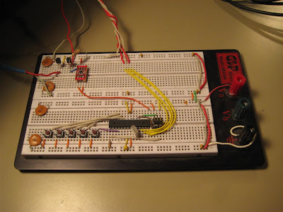
The controller consists of two main parts: The AVR-based controller breadboarded by my bed, and the TRIAC junction box under my desk.
Three of the four channels are in use.
Screw terminals for connecting the low voltage control lines. The box was designed to reliably run on either 3V or 5V without requiring external current-limiting resistors.
TRIAC control board:
Each optoisolator 8-DIP contains two channels (thus why the part number ends in -2)
Standard duplex 15A outlets from ACE. Note that I cut out the bus bar between the top and bottom outlets to separate their hot conductors, allowing me to control them individually.
Source code:
ALSO NOTE: Since all of the 120VAC equipment I build plugs into the wall and is not hard wired, I in NO WAY violate the NEC, as this is all "temporary" wiring. This means I do NOT want to read any comments about how this will void my fire insurance or how unsafe this project is, without a specific critique as to how to improve it (A choice place for improvement would be in the TRIAC triggering circuit, for which I could not find a concise application note as to how to use the TRIACs, which is why the schematic is deliberately vague there. I've seen a lot of crazy stuff, including BJTs, capacitors, and several resistors, with no explanation as to their purpose. I very carefully watched my circuits for the first few days and severely derate it.)
This is an on-going project involving the lighting situation in my room. I live in an apartment which doesn't have any overhead lighting in the bedrooms, which means I have to light my room with several lamps scattered throughout the room. This would be fine, except that the outlet controlled by the light switch is in quite possibly the least useful place based on my room's arrangement. This means all of my lamps are individually controlled, and the light switch controls none of them. One of them didn't even have a switch on it, so I had to hack one together from spare parts.

This post covers only the initial, crude version of this project. At this point it does nothing other than turn the lights on and off at command. Future enhancements will be documented as they happen.
Video:
Currently, there is individual buttons for each of the three lamps, and a circuit to monitor the switched outlet across the room. Pressing any of the buttons will toggle the respective lamp. A positive edge on the light switch will turn a select two of the lamps on, regardless of the current state of the lamps. A negative edge on the light switch will turn off all lamps. This makes the light switch useful again, as it allows it to turn on a useful set of lights on entrance to the room, and turn off all lights on exit. If the light switch is in the wrong position (up when a positive edge is needed), all you have to do is switch it down, and back again.
The controller consists of two main parts: The AVR-based controller breadboarded by my bed, and the TRIAC junction box under my desk.
- The AVR watches for button presses from five push buttons (only three are function as of yet, toggling individual lights), and changing edges on the input from the switched outlet. The switched outlet powers a 5V power supply, which then feeds a 3.3V linear regulator, since this entire project runs on 3.3V. An AC wall wart would allow for detecting the light switch being turned off earlier, since the DC power supply has filtering capacitors (thus the 100 ohm pull-down resistor), but I didn't have one handy, and would require the increased complexity of watching for changing edges and then deciding when the switch is turned off based on a lack of edges.
- The TRIAC junction box has four independent channels to switch low current (<10A) 120VAC, using pairs of optoisolated TRIACs and power TRIACs in TO-220 packages. TRAICs can be used to dim lights, but my optoisolators have zero-cross detectors in them, so there is no way to phase the output of the TRIACs (Informative GIF from Wikipedia).
Three of the four channels are in use.
Screw terminals for connecting the low voltage control lines. The box was designed to reliably run on either 3V or 5V without requiring external current-limiting resistors.
TRIAC control board:
Each optoisolator 8-DIP contains two channels (thus why the part number ends in -2)
Standard duplex 15A outlets from ACE. Note that I cut out the bus bar between the top and bottom outlets to separate their hot conductors, allowing me to control them individually.
Source code:


