Rubidium Frequency Standard Enclosure
At the beginning of the year, Dave Jones did a very interesting tear down video of a FE-5680A Rubidium frequency standard. Rubidium standards are a type of atomic clock, which are able to keep very accurate and stable time. While not as good as cesium clocks, rubidium references are still able to keep time on the order of 2x10^-10, which works out to be 6ms of drift per year.
Normally, rubidium standards are very expensive, but it is possible to find these modules on eBay for $50-$100 as they come out of decommissioned equipment (such as cell phone towers, which need this level of time stability). On a hobbyist bench like my own, these standards are useful as a very good time base to calibrate other oscillators against. They’re also useful because 10MHz is the standard time base used by bench test equipment, so this standard can be used to drive frequency counters and spectrum analyzers via their time base ports so that they are more precise than with their stock internal 10MHz oscillators.
When you buy the module on eBay, it comes as a sealed package with a single DB-9 connector on the side for power in and signal out.
- 15V-18V, 2A
- GND
- Signal Lock (active low, high impedance)
- 5V, 100mA
- GND
- 1 µs long pulse per second output (TTL compatible)
- 10MHz 1Vp-p
- RS-232 Rx
- RS-232 Tx
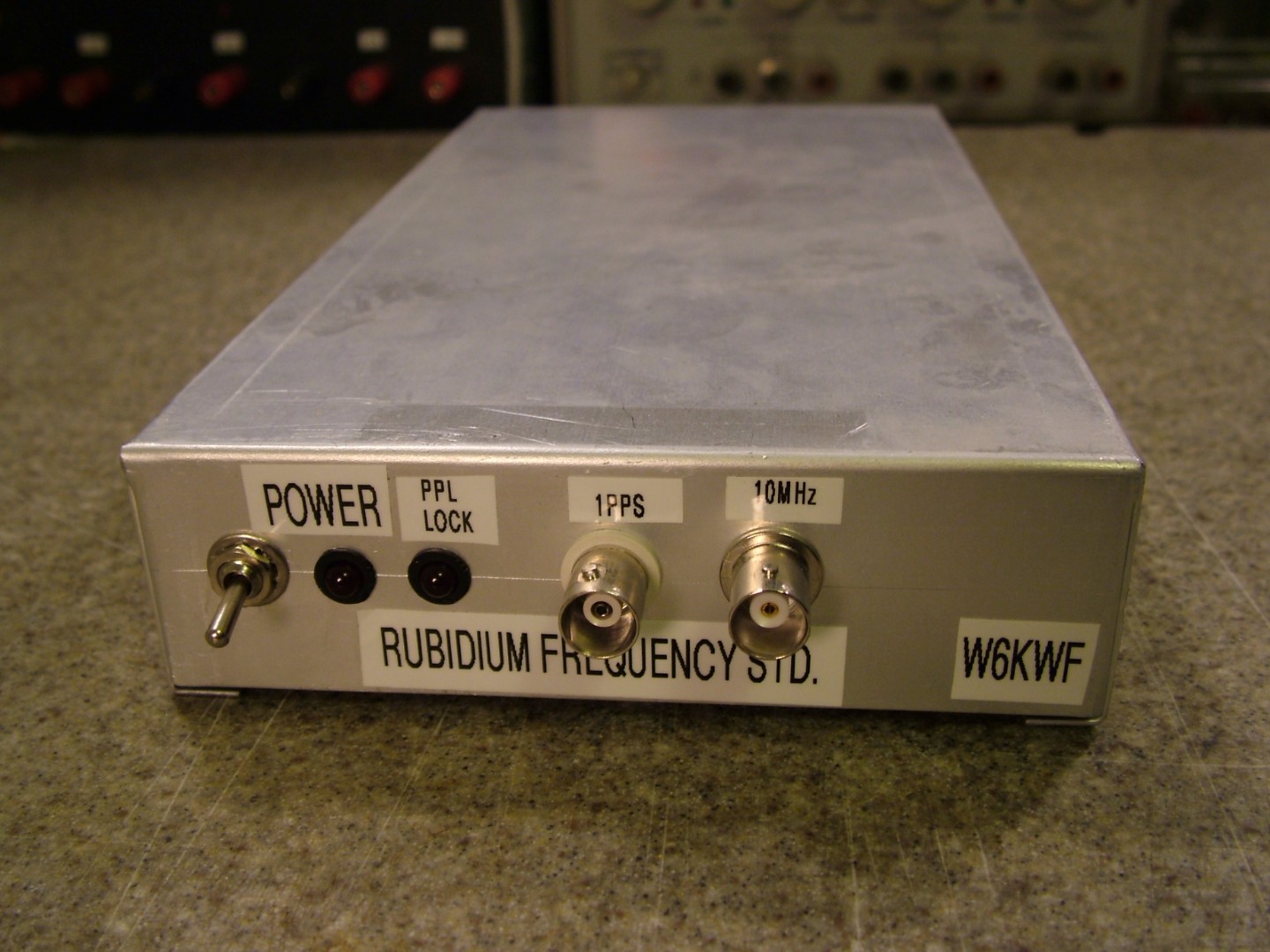
After accidentally blowing up one of these standards when fly-wiring these power connections (The FE-5680A does not like 15V applied to the 5V pin), I decided to build an enclosure around it, so that powering it up now only consists of plugging in a 16V laptop power supply, flipping a switch, and waiting for it to heat up enough for the PLL LED to light.
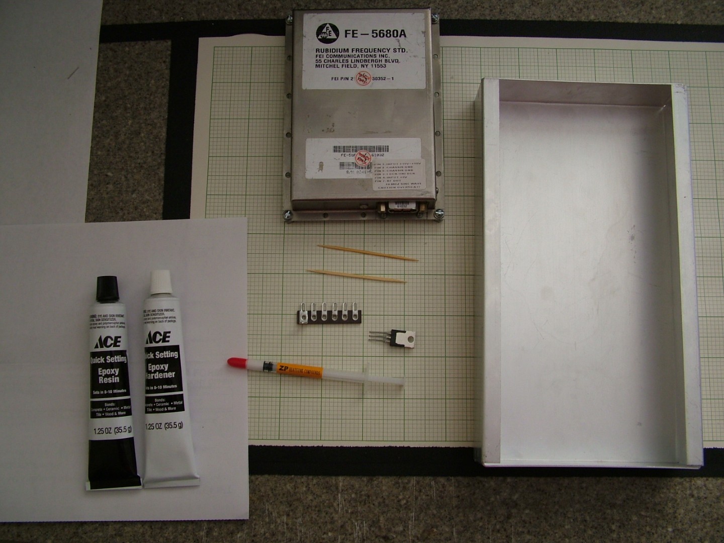
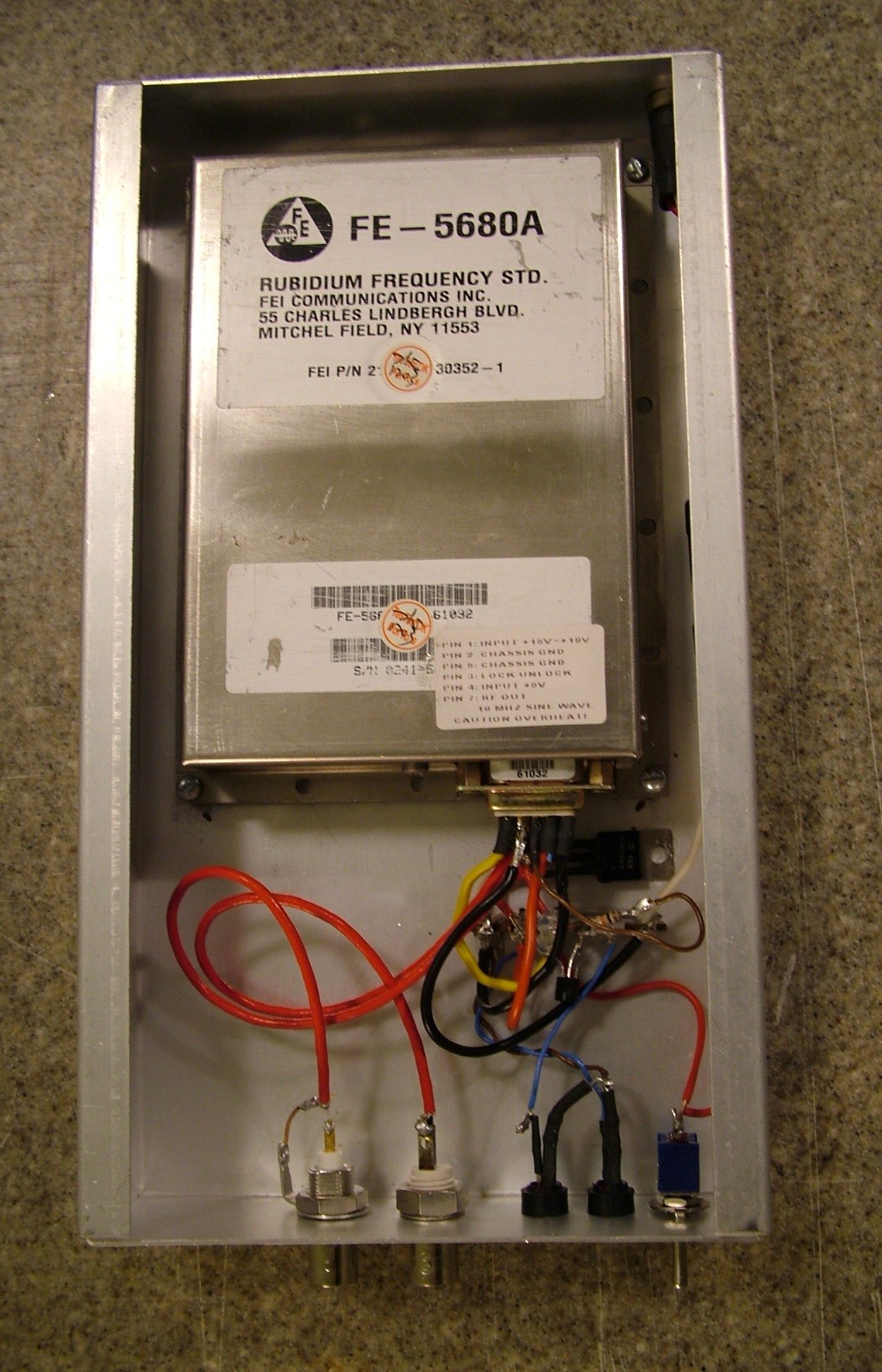
I glued threaded standoffs to the inside of the case to mount the FE-5680A on, but glued the 7805 linear voltage regulator for the TTL supply directly down to the case, since it’s less likely I’ll ever want to scavenge the 50 cent regulator than the $75 frequency standard module.
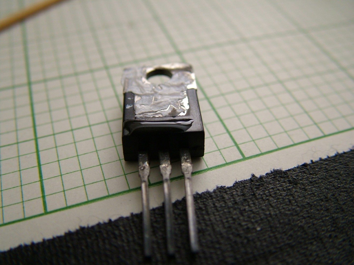
I used an interesting trick that one of my amateur radio friends taught me this summer about how to get good thermal contact between a power package and a metal case without drilling into the case. Apply thermal paste across the majority of the case (A TO-220, in the case of a 7805), but carefully leave two opposite ends free of thermal compound. Apply two small dabs of epoxy on the free corners to fix the package down, without needing any sort of special thermally conductive cement to maintain good thermal contact.
A couple things to note about the rest of the build which are important:
- The FE-5680A gets hot. This is on purpose. Many people mount it to a heat sink when they enclose it, but don’t realize that the FE-5680A is thermostatically heated, so any heat sink you attach to it will only cause it to draw more power until it has reached the same temperature.
- The loop lock indicator (pin 3) is both an input and an output. It goes low when the standard has achieved phase lock with its rubidium lamp, but will stay unlocked as long as you externally hold the pin high. This means that you can’t use this pin to directly drive an LED, but need to buffer the LED with a transistor. I used a 2N3906 PNP transistor, and a 10k resistor from the transistor’s base to pin 3.
Some other useful links for the FE-5680A: