Design Project: Zombie Tag Repeller
During my daily browse-the-internet-because-I’m-bored session a few days ago, a question came up in the electronics subreddit. BovingdonBug is trying to build a “zombie repeller” for his (?) kids. This question caught my eye for a few reasons: He didn’t tell us to solve his problem in broken English, it’s an actually reasonable first project in electronics, and he posted a beautiful info-graphic with it. Click to enlarge:
Since he is building five or six of these, he asked to keep the budget in control. Considering that I’ve been pounding electrical nails in with the sledgehammer that is the Arduino all quarter, I figured some down-to-the-metal digital logic would be a good change of pace.
Changing the design for the different feature sets (random length cycles vs fixed, single lit light vs flashers) is pretty trivial, so I’ll give you a solution for each one. There is certainly other ways to do each step, and the component values I’m giving you are just what I stuck in my breadboard that worked. I know that they could at least be optimized to improve battery life, at the cost of wave symmetry, which I find unacceptable, but you may be less hellbent on symmetry1.
Power Supply
Many of these stages only use a 555 timer IC, which can take up to ~15 volts from the supply. If this ends up being the only IC you use, you could freakin hook this thing up to a car battery (with the right LED resistor values). In any case, my personal choice would be to use three or probably four AA batteries in a battery holder. With NiMH batteries, this will get you 4.8 volts, which is perfect for TTL.
Parts list:
- 4 AA battery holder with leads (digikey)
Lights
For all of the different timing circuits we’re about to build, they do little to no good if they don’t make anything light up. This being the 21st century and all, the popular thing to make light up in these type of projects are light emitting diodes (LEDs). A normal diode is a device which only allows current to flow in one direction. A light emitting diode behaves exactly the same, but when current is flowing, it creates light. There is ways to tell which way is conducting in an LED2, but it’s usually pretty easy to just try it one way, then reverse it if it doesn’t work.
The problem is that diodes have the advantage of letting as much current flow as possible. If you look closely at an LED, you can see the small gold wire connecting the two leads, and it’s really freaking small. If you aren’t careful, you can easily push enough current through an LED to melt that wire, and burn the epoxy case, rendering the LED less light emitting, and more useless. The question then becomes, “How to prevent too much current from flowing through an LED?”
Current Limiting Resistors: The cheapest solution is to use a current limiting resistor. A current limiting resistor is exactly like any other kind of resistor, but happens to be used to limit current, as opposed to other possible applications for a resistor, such as a voltage divider, or heating element, or pull-up or pull-down resistor in digital logic. To calculate how big your current limiting resistor needs to be requires a few pieces of information. You need to know the voltage drop across the LED, the supply voltage, and the amount of current you want to have flowing through the LED when it’s turned on. Typical values for a red LED are a 1.8V drop across the diode, and a 20mA rating.
The equation you use is Ohm’s law. Ohm’s law states that the voltage across a resistor is the product of the current through the resistor and it’s resistance (V=IR). Let us say that you want to calculate what size of resistor to use for a typical red LED from a 5V supply, which is a very standard voltage, and close to what we’ll get from 4 NiMH batteries. Solving for the needed resistance, we get R = V/I, but what is the voltage across the resistor? The power supply voltage minus the LED voltage drop, so 5V - 1.8V = 3.2V. We want to have 20mA flowing through the LED, so plugging those into Ohm’s law gives us R = 3.2V / 0.020A = 160Ω. Notice that this is nothing more than a guide as to what value to use. Feel free to push your luck and use a smaller value (not recommended), or be conservative and use a larger value resistor (I typically use 330Ω resistors for my indicator lights). You also will usually stand a very poor chance of getting the size resistor you calculate. Engineers have very carefully selected 24 typical values for each order of magnitude, so although you may not be able to get your exact value, you can get something very close to it.
Since these lights are going to be outside, I would think you’d want them to be as bright as possible without risking damaging them. I would also probably install several of them per box, using a separate resistor for each one. If you do have several LEDs per circuit, make sure to check that the output current rating of whatever is driving them can handle it. 555s are usually rated for something like 150mA output, so you could easily drive 4-5 LEDs per 555. 7400 logic gates, which we’ll get to later, only put out 25mA, so driving LEDs directly from those wouldn’t be as great an idea.
Parts list:
- High intensity red LEDs
- A current limiting resistor to be put in series with each LED.
Version BX - LED lights for a fixed length of time
For this version, we are going to have the zombie repeller turn on for a fixed amount of time, and then turn off for a fixed amount of time. When it’s on, it will turn the lights on solid, then turn them off at the end of the cycle. To do this, we’re going to be using the classic 555 timer IC, which is a chip that times how long it takes to charge or discharge a capacitor through a set of resistors. The 555 can be configured to do this in several different ways, but the form that we’re interested in is the “astable mode.” In this mode, the 555 continually alternates between a HIGH and LOW output, from now until the cows come home.
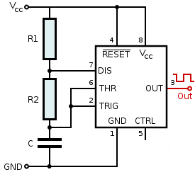 Photo credit: Wikipedia
This is perfect for our repellers, since we want them to continually turn on and off throughout the game. Now all we need to do is calculate the values needed for the capacitor and two resistors that set the frequency. Since we’re shooting for something like a 2 minute period, a good starting point would be a big electrolytic capacitor on the order of 1000μF. You then plug this, and your target frequency (0.00833Hz = 1/120 seconds) into the frequency formula for the 555, and solve for the needed resistance:
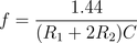
The result you should get is that R₁ + 2R₂ = 172.8kΩ. If you didn’t get this, make sure you used the capacitors value in Farads (0.001F, not 1000μF, “micro-farads”). Now you just need to pick resistors to get a resistance kind of close to this calculated value.
When picking these values, realize that the HIGH time is a function of R₁ + R₂, while the LOW time is just a function of R₂. This means that if you pick equal values for both R₁ and R₂, the repeller will be on for 2/3 of the time (which may not be a bad thing, depending on what you want). At the same time, both resistors must be at least 1kΩ, or else you can damage the 555. To get as symmetrical of an output as possible (HIGH and LOW times both about the same length), I picked 1kΩ for R₁, and then something a few orders of magnitude larger than that for R₂. Digging through my parts box, the closest I managed to come up with was a 56kΩ resistor for R₂, which means that the HIGH time is less than 2% longer than the LOW time, which isn’t noticeable (or even a concern, if you don’t care). This is smaller than the calculated value of 85kΩ, but that just means it’ll turn on and off a little faster than 2 minutes.
Now that we have an output that turns on and off about once a minute, all we need to do is connect it to some LEDs. I already explained how to calculate what size of resistor you need, so take that, and hook it up as 555 output - LED - resistor - ground or 555 - resistor - LED - ground. Feel free to connect several LEDs to the output of the 555, since it can deliver quite a bit of current.
Parts list (per box):
- 1 555 timer IC (digikey)
- 1 large capacitor (100-5000μF) (digikey) (Pay attention to the cap’s voltage rating, and note that there is a stripe down the negative side, and it’s important to connect that side to ground)
- 1 1kΩ resistor*
- 1 large (50k-100k) resistor*
- 4 LEDs
- 4 current limiting resistors (~200Ω)
* These values are what I picked. Like everything else here, these are just suggestions. Feel free to change them as you wish.
Version BY - A pair of LEDs flash back and forth for a fixed amount of time
This is going to build upon the BX version, so getting that working first wouldn’t be a bad idea. BX just turned on the LEDs directly. Instead of connecting the output of the 555 to LEDs, consider connecting it to a second 555, tuned for a much higher frequency (2Hz), which is connected to LEDs. For ~2Hz, I used a 10μF capacitor, and a 1k and 56k resistor.
To switch the second 555 with the first, connect the output of the first to the “RESET” pin on the second. When the reset pin is grounded, the output will be LOW, and the oscillator will stop. This means that where we used to have the 555 light an LED, we’re now having it turn on a second 555, which turns on and off an LED much faster.
Finally, we want a second set of LEDs, possibly of a different color, to light up alternating with the first set. To do this, we are going to take advantage of one of the properties of the 555 output, that it can both “source” and “sink” current. Sourcing current is what we have been doing so far; the output goes HIGH, current flows out, through the LEDs, to ground. Sinking current is a little harder to understand, but is just the opposite. When the output on the 555 is LOW, current can flow back into it from another LED attached to a higher voltage than ground. Connect both sets of LEDs, and one will light when the output is HIGH, and the other when it’s LOW (See diagram on the right).
The problem you will soon notice is that, since the output is held LOW when the RESET pin is low, this second set of LEDs will stay lit when the device isn’t active if you connect them directly to the battery. Where could you connect the positive side of the “sink” LEDs so they only turn on when the device is active? (Answer: note 3)
Parts list (in addition to previous lists):
- A second 555 timer (or a 556, which is two 555 cores in one chip) (556 on Digikey)
- 1 small electrolytic capacitor (10μF)
- 1 1k resistor
- 1 56k resistor
- A second set of LEDs and current limiting resistors
Going further
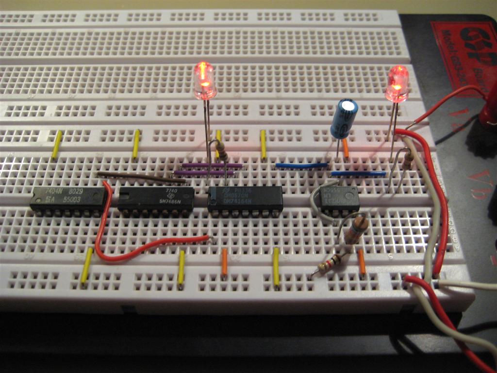
Unfortunately, I’ve restarted class, so I have much less time to work on projects on this site. I’ve built a random circuit, and taken some videos of it, but explaining it would take much longer. It uses three digital logic gates, but time dictates I say little more about these more complicated versions of the repellers.
Logic gates used:
Note that I tested it with N family TTL gates, so using HC gates is untested, but should work.
| Video 1 | Video 2 |
I’m sorry I can’t fully explain these as of now, but hopefully this all gives you some good ideas.
References: TTL Cookbook by Don Lancaster. Going into this book with a good fundamental understanding of electronics, this should be all you need to have come up with my solutions. Not only did I learn everything about the 555 from this book, but all of the digital logic blocks came from this.
-
The classic solution to making a symmetric waveform is to use the 555s to drive a JK flip-flop, which means the frequency is half of what it was, but perfectly symmetric. I don’t think this is particularly important for this application. ↩
-
The side that needs to be connected to the positive voltage will usually have a longer lead when new, and the clear epoxy case will have a flat spot on the ground side. ↩