Switched 120V Outlet Junction Box
After spending 4 months worth of my free time playing with 5V electronics, I figured it’d be a nice change of pace if I started doing stuff with real 120VAC electricity.
For my first project, I figured I’d build something I’ve needed all year; one of my desk lamps doesn’t have a switch (it came out of a dumpster, like so much in my apartment). Plugging and unplugging it works, but isn’t the ideal solution. Last year, my dad built his mother a junction box with a wall switch in it so that she could turn on and off her lamps without requiring the dexterity needed to rotate the small knobs on the lamps themselves. He was kind enough to let me pull supplies out of his junk boxes for this project, so I was able to completely do this from stock:
Parts list:
- 1 spare 3 conductor computer power cable. I cut off the chassis connector on the end and connected the three wires (black - hot, white - neutral, green - ground) to the switch and plug.
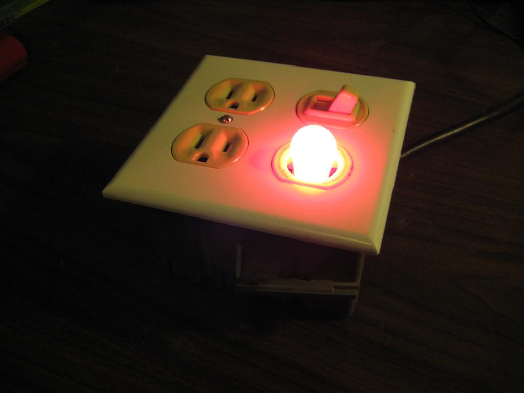
- 1 wall switch. I found one that has an awesome pilot light with it, but a normal single toggle switch would work.
- 1 wall socket.
- 1 double face plate fitting your socket and switch. Different styles of switches will need different face plates, and there should be a whole selection of them at your hardware store.
- 1 double junction box.
- 6 6-32 machine screws to close it all up.
- 1 or 2 short pieces of heavy gauge wire (14 or 12 should do it).
The first thing to do is to cut the chassis connector off the computer power cable. Cut back enough of the insulation (and possibly braided shielding) to expose the three conductors. Assuming you have an American cable, the three wires should be colored black, white, and green. Before connecting the power cable to the switch or outlet, be sure to feed it through one of the holes in the side of the junction box. If there isn’t any holes in the side of your junction box, that’s fine, just take a screw driver and MAKE a hole to feed it through. There should be about eight perforated places where you can punch out the plastic.
- The black wire is the hot wire. This is the one that generally hurts, and should not ever be touched by such conductive things as human fingers, toes, arms, heads, etc. This wire gets connected to the switch, since we want to switch the hot line, and not the neutral, or else whatever we have plugged into it will still be dangerous, even when this box is switched off. If you were just wiring up the outlet without a switch, you would connect this wire to the brass screws (yeah, even the screws are color coded, how awesome is that?).
- The white wire is the neutral. This one gets connected to the tin screws on the outlet, which are the ones on the left, facing the outlet (the larger slot in 15A circuits, or the T shaped one in 20A circuits (like in your bathroom)).
- The green wire is ground. This is different from neutral in that it isn’t meant to carry any current. If it does, something is going very wrong, and is refereed to as a ground fault. Most modern outlets use GFCI, which is a device that can very quickly sense if there is a mismatch between the in and out current in a circuit and disconnect it. As excellent example of when this would trip would be when some of the electrical current decides it would be much more awesome to flow through your body to ground, instead of back through such troublesome things as wires. These are the outlets with the black and red buttons on them.
- You might also find an unshielded wire in the cable. This is a ripcord, designed to be used to remove the insulation. I didn’t even know this existed until I had finished cutting off the outer insulation with a razor blade. Just cut this back to the insulation.
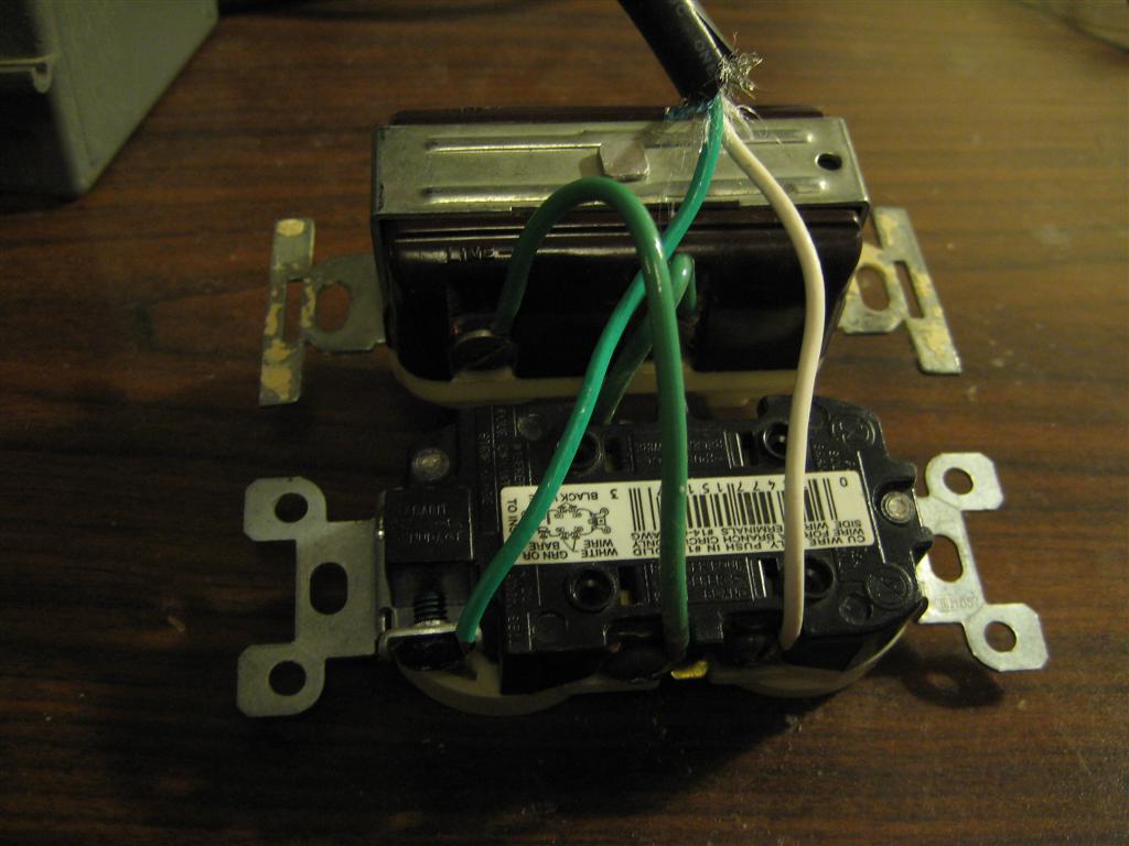
After those three wires are connected, the last thing to do electrically is to jumper between the switch and the hot (brass) side of the outlet. I incorrectly used green wire to do this. Luckily, this is “temporary wiring,” (since it can be unplugged from the wall) so it doesn’t have to be code compliant, just safe. Also, since my switch has a light in it, I needed to connect this to neutral as well, which I did with a second piece of green 14 gauge wire.
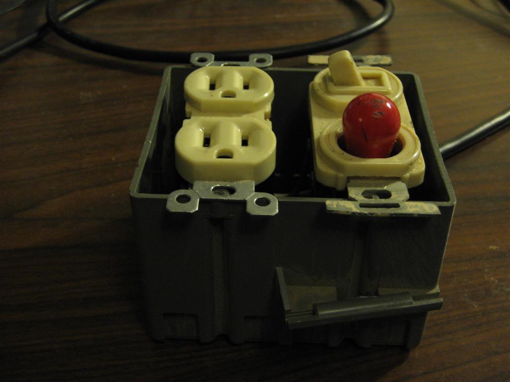
Now that we’re done with the electrical part, all that’s left is to screw it all down into the box, and test it (might want to test it before you screw everything it, depending on how lucky you’re feeling tonight). The main thing to test is that each of the contacts on the cable are connected to the matching hole in the socket, and that the switch turns off the right one. It would also be prudent to make sure that the red indicator light actually turns off when you throw the switch; not that I would make such a foolish mistake as to assemble this entire project, then consider that 50% isn’t very good odds on picking that direction.
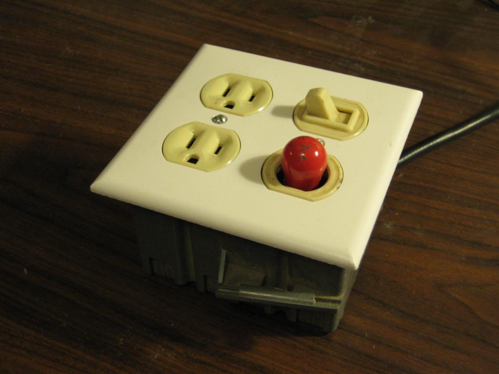
And there it is! A switched outlet, useful for anything that you need to physically remove from power, but don’t want to continually unplug.
Things I would possibly change:
- I didn’t think about it, and just grabbed the first computer power cable I found in my junk box, which turned out to be 18AWG, which is a little small. The extra wire I used was 14 gauge, which is fine, but not perfect. This entire project should be done in 12AWG wire, so as you’re collecting parts for this, keep that in mind.
- If you look on the side of outlet pairs, you’ll notice that they have two screws on each terminal, with a small metal tab between them. If you break out the tab on the hot side, you can electrically separate the two plugs. You can then have one always be hot, or use a double switch to have two individually switchable outlets, if one channel isn’t enough for what you want to do with it.