Intelligent Fan Controller
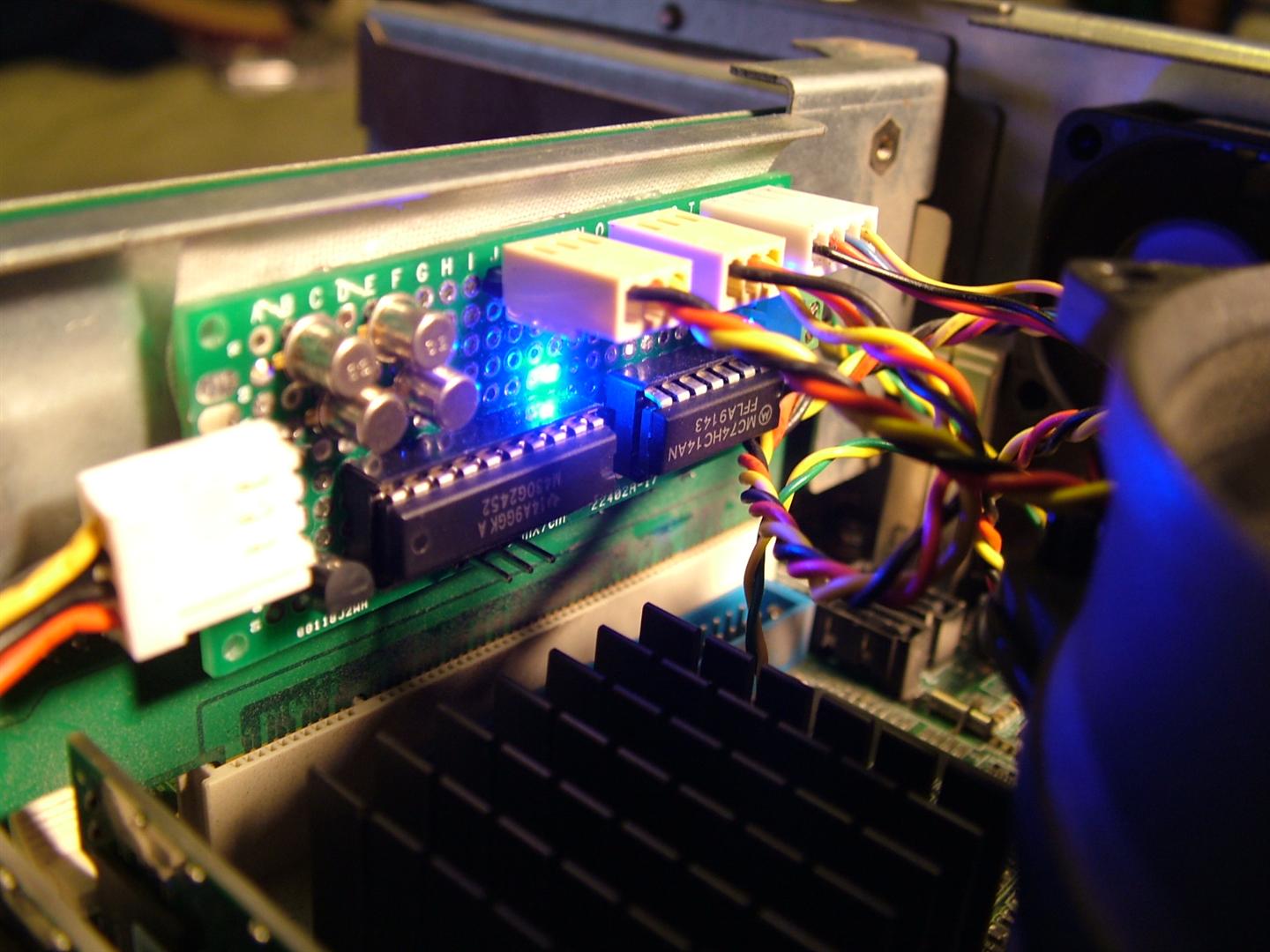
During the Maker Faire Salvage Crawl last month, I picked up a kiosk-size industrial computer for $20. All well and good, except that the BIOS in it made no effort to control the fan speeds, and instead simply ran all three cooling fans at full blast. This was unpleasantly loud, so I decided to simply build my own fan controller, using an MSP430, so I could easily monitor the system temperature and adjust the fan speeds accordingly.
As a bonus, while waiting for the computer to heat up, I give you a basic intro to the concept of a PID controller.
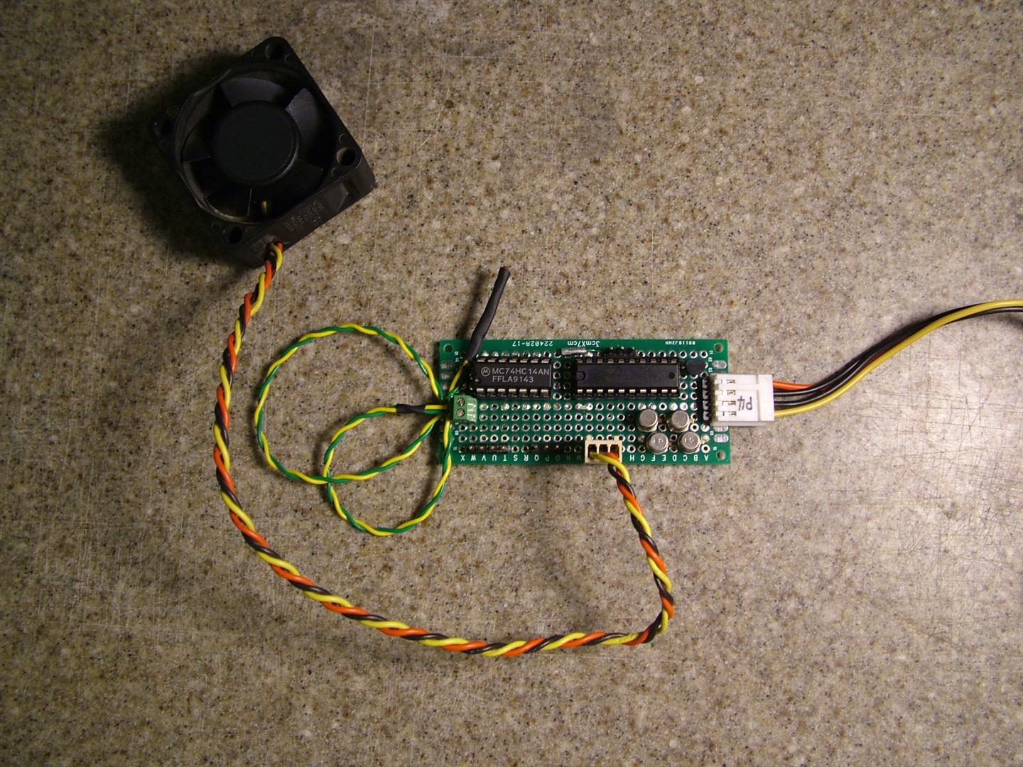
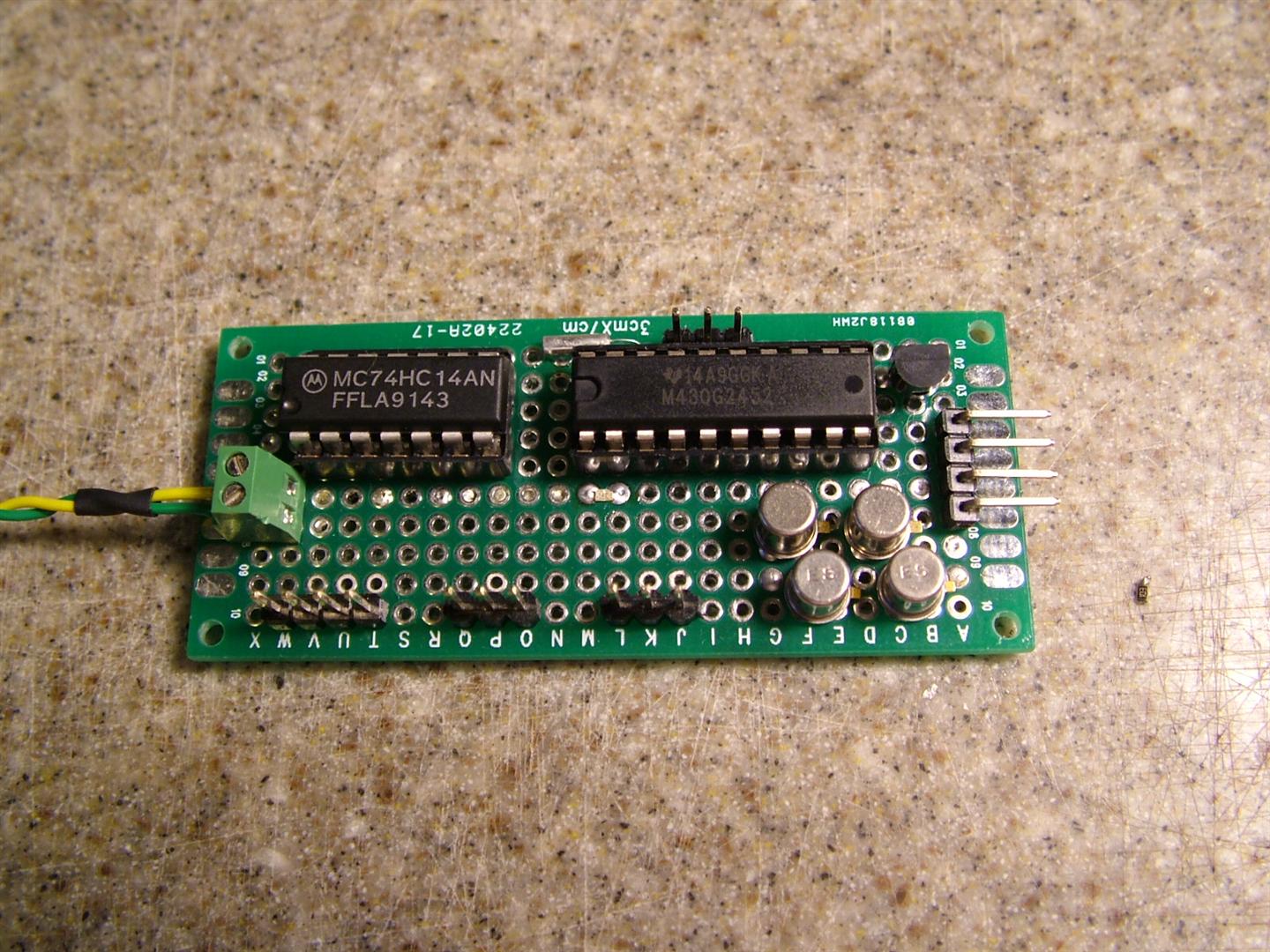
The hardware isn’t too involved; an MSP430G2452 takes temperature readings from the CPU via a 10k thermistor, then uses this to set the fan speeds for the three fans.
Computer fans typically come in two varieties; three pin and four pin.
- Three pin fans have, in order, a ground, a 12V supply, and a tachometer pin. By applying a pull-up resistor to the tach pin, the fan outputs two pulses per rotation, so the MSP430 can count these pulses and know how fast each fan is spinning. To adjust the speed of the fan, the MSP430 pulse-width-modulates the 12V pin at 32Hz.
- Four pin fans are backwards compatible with three pin fans, with the addition of a fourth pin for speed control. Instead of requiring the pair of transistors to switch the 12V line as in the case of the three pin fans, you can instead simply apply the 3.3V PWM signal to this fourth pin and the fan will use it to modulate its power itself.
This computer happened to come with two three-pin fans and a single four-pin fan, which is why I only needed two NPN-PNP transistor pairs, to switch the two three-pin fans. The four-pin fan is controlled directly from the MSP430 digital output.
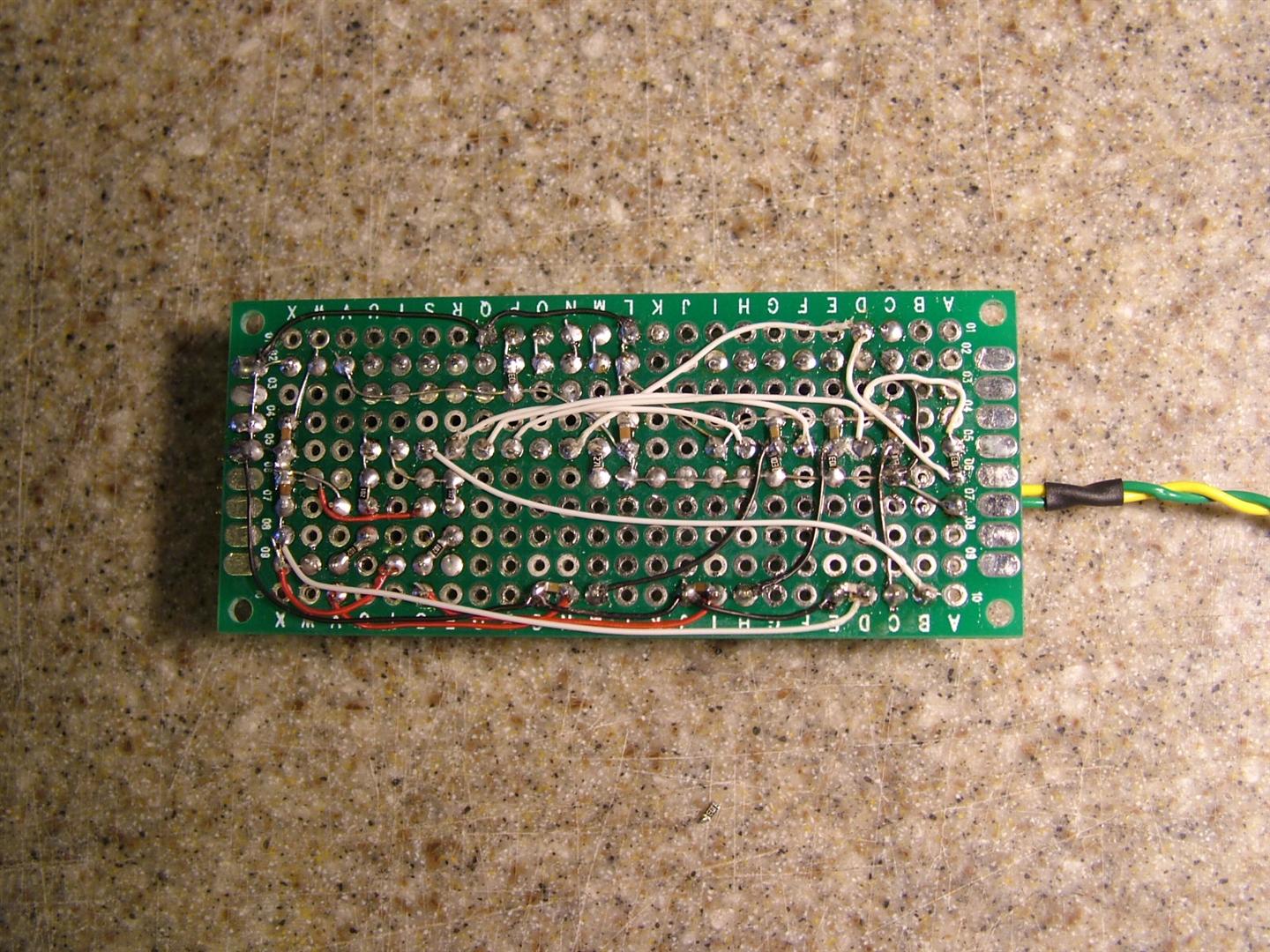
I have moved almost entirely to using 0603 surface mount passives on my prototype projects; fitting circuits on perf board is much easier when you can fit passives like resistors or capacitors between any two adjacent pins.
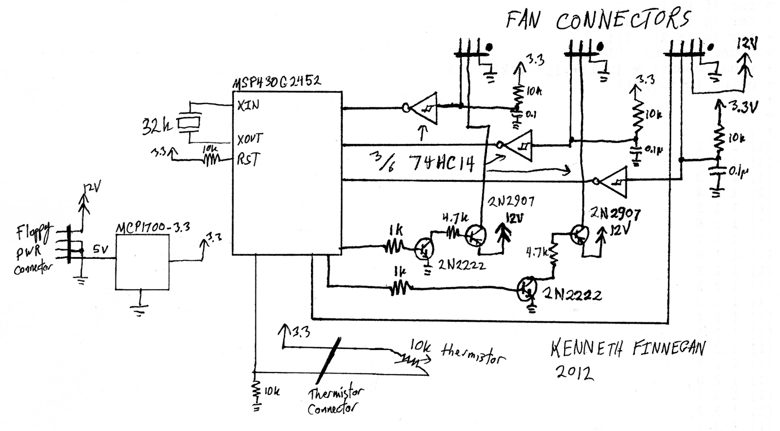
In the schematic, I forgot the input 10μF caps on the 12V and 5V lines. The entire circuit board is powered using the standard 0.1” floppy disc power connector (12V (yellow), GND, GND, 5V (red)), since those tend to be numerous and under-utilized inside desktop computers.
One thing to appreciate when reading my code is that I have very deliberately left the control code weak. It is currently a purely integral controller, which has many disadvantages which can be improved via switching to a PI controller and implementing integral spool-up prevention. I’m considering revisiting this project with another hardware revision and some controller algorithm refinements, but alas the hazard of having this one “mostly-working” means that may take a while… I’ll leave programming a faster temperature control loop as an exercise for the reader.
Source code:
#include "msp430G2452.h"

#define	FAN_CNT		(3)
#define PWM_FREQ	(32)
#define PWM_RESS	(128)

// Port 1
#define	LED1	(1<<0)
#define	TMP_RX	(1<<1)
static const int TACH[]	= { (1<<3), (1<<4), (1<<5) };
// Port 2
static const int FAN[] = { (1<<0), (1<<1), (1<<2) };

#define LED1_ON()	(P1OUT &= ~LED1)
#define LED1_OFF()	(P1OUT |= LED1)

volatile struct {
	int second;
	int fracofsec;
	unsigned int rpmdata[2][FAN_CNT];
	unsigned int maxrpm[FAN_CNT];
	unsigned int fanpwr[FAN_CNT];
	unsigned int fanrpm[FAN_CNT];
} fs;

void tempCTLAlg(void);
int bound(int low, int mid, int high);
int takeADCReading(int channel);

void main(void) {
	// Kill Boris - we don't need a watchdog
	WDTCTL = WDTPW + WDTHOLD;

	// Clock system
	DCOCTL = CALDCO_16MHZ;
	BCSCTL1 = CALBC1_16MHZ;
	BCSCTL2 = SELS; // DCO slave clock

	// Timer A
	TA0CTL = TASSEL_2 | MC_1; // SCLK, UP
	TA0CCR0 = (32768 / PWM_FREQ / PWM_RESS) - 1;
	TA0CCTL0 = CCIE;

	// ADC10
	ADC10CTL0 = SREF_0 | ADC10ON; // Vcc reference
	ADC10CTL1 = INCH0 | ADC10SSEL1; // Channel A1, MCLK
	ADC10AE0 = (1<<1);

	// IO Port 1
	P1DIR = LED1;
	P1IE = TMP_RX | TACH[0] | TACH[1] | TACH[2]; // Enable ints
	P1IES = 0xFF; // H-L transition int
	P1IFG = 0x00; // Clear noise interrupts

	// IO Port 2
	P2DIR = FAN[0] | FAN[1] | FAN[2];

	// Start interrupts
	_BIS_SR(GIE);
	int i;


	// Three second startup at full power
	for (i=0; i<FAN_CNT; i++)
		fs.fanpwr[i] = PWM_RESS;
	while (fs.second <3) ;
	for (i=0; i<FAN_CNT; i++) {
		fs.maxrpm[i] = fs.rpmdata[1][i];
		fs.fanrpm[i] = 2 * fs.maxrpm[i] / 3;
	}
	fs.fanrpm[0] = fs.fanrpm[0] / 2;


	while (1) {
		if (fs.second) {
			fs.second--;
			tempCTLAlg();
		}
	}
}

// Temperature Control Algorithm
// Do the 1Hz work to try and keep the temperature on target
void tempCTLAlg(void) {
	int tempsense = takeADCReading(1);
	int lightvote = 0;
	int i;

	int tempDelta = tempsense - 280;

	for (i=0; i<FAN_CNT; i++) {
		fs.fanrpm[i] = bound(fs.maxrpm[i]>>2, fs.fanrpm[i] + tempDelta, fs.maxrpm[i]);
		int rpmDelta = fs.rpmdata[1][i] - fs.fanrpm[i];
		fs.fanpwr[i] = bound(0, fs.fanpwr[i] - (rpmDelta/250), PWM_RESS);

		if (rpmDelta < 0) { // too slow
			lightvote++;
		} else {// too fast
			lightvote--;
		}

	}

	if (tempDelta > 0) {
		LED1_ON();
	} else {
		LED1_OFF();
	}
}

int bound(int low, int mid, int high) {
	if (low > mid)
		mid = low;
	if (high < mid)
		mid = high;
	return mid;
}

int takeADCReading(int channel) {
	ADC10CTL1 = (ADC10CTL1 & 0x0FFF) | (channel << 12);
	ADC10CTL0 |= ENC | ADC10SC;

	while (ADC10CTL1 & ADC10BUSY) ;

	return ADC10MEM;
}

#pragma vector=TIMER0_A0_VECTOR
__interrupt void Timer_A00 (void) {
	int i, fracofpwm;
	fs.fracofsec = (fs.fracofsec + 1) % (PWM_FREQ * PWM_RESS);
	if (fs.fracofsec == 0) {
		for (i=0; i<FAN_CNT; i++) {
			fs.rpmdata[1][i] = 30 * fs.rpmdata[0][i];
			fs.rpmdata[0][i] = 0;
		}
		fs.second++;
	}
	fracofpwm = fs.fracofsec%PWM_RESS;
	if (fracofpwm == 0) {
		// Turn on enabled fans
		P2OUT |= FAN[0] | FAN[1] | FAN[2];
	}
	for (i=0; i<FAN_CNT; i++) {
		if (fs.fanpwr[i] < fracofpwm) {
			P2OUT &= ~(FAN[i]);
		}
	}
}

#pragma vector=PORT1_VECTOR
__interrupt void Port1 (void) {
	unsigned int pins = P1IFG;
	P1IFG = 0x00;

	unsigned int i;
	for (i=0; i<FAN_CNT; i++) {
		if (pins & TACH[i]) {
			fs.rpmdata[0][i]++;
		}
	}
}