No Name LCD
So as part of my shopping trip at Halted, I bought a Liquid Crystal Display. It’s a 2x16 alpha-numeric display that I’m planning on hooking up to my Arduino (once it comes). Here is a good tutorial on hooking up LCDs to PICs, which will be helpful.
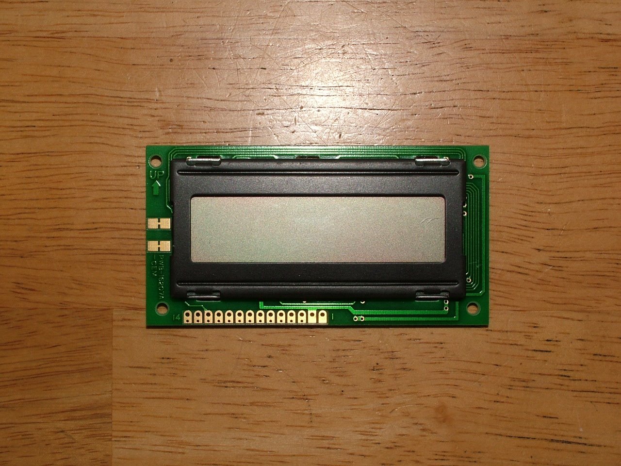
So step one is to try and figure out what I’ve got. I googled for every number on that PCB, and this is some cheap, old, no-name LCD.
The markings on the board are:
PWB-16207A -CEM 9735H4 DMCI6207 OPTREX JAPAN RU(R) E91964 3135L:.
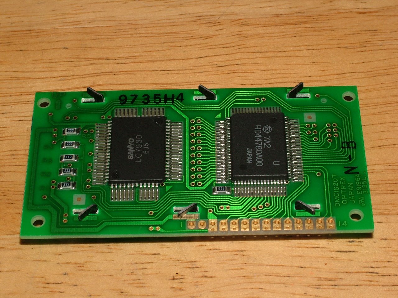
Since there was no data sheets for the whole unit to be found, I needed another way to figure out the pin out on the board. Next step was to look at the two ICs on the back.
First chip:
7A2 U HD44780A00 JAPAN
Second chip:
SANYO LC7930 6J5
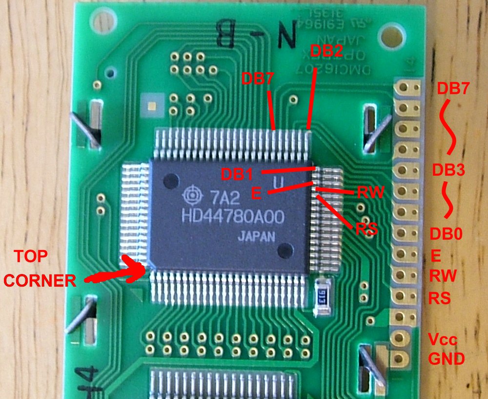
Luckily, starting with the HD chip was a good call. Turns out this is a very popular LCD controller. It’s a very OLD LCD controller, but it’s still pretty popular. Here is a data sheet for the HD44780 series.
So on page 4, they show the pinout for the FP-80B package, and it was only a matter of following the traces on the PCB from the chip out to the edge of the board. That took care of the DB0-DB7 lines, the E, RW, and RS lines, and finally Vcc and GND. The Vcc and GND was a little more challenging because it went onto the front of the board, but luckily never slipped under the LCD itself, so I was still able to follow it.
FYI: It looks like the LC7930 is the LCD driver chip, where the HD44780 is the controller that handles the interface between the driver and the host device.
So finally, the contacts on the PCB are numbered from 1 to 14:
- GND
- Vcc
- Contrast - tie to ground with resistor
- RS
- RW
- E
- DB0
- DB1
- DB2
- DB3
- DB4
- DB5
- DB6
- DB7
So after all the tracing, the only pin left was #3, which I am guessing is the contrast control. To adjust this, I’ll either hook it up to the center tap of a variable resistor between Vcc and GND, or just hook it up to a PWM pin on the Arduino.
DISCLAIMER: I don’t have my Arduino yet, and have yet to test this pin out. If I happen to be wrong, and you toast your LCD, I’m sorry, but you can’t hold me responsible. Use at your own risk, these are only a good guess.
Update: I’ve gotten my Arduino, hooked it up, and was correct on all pins. I got good results on the contrast pin by only grounding it with a 360 ohm resistor. By default it only displays one line, but Jeff Glass and I have been working on all of the commands to get it to do more.